Image Rotation
| date: | March 18, 2006 |
|---|
How do you rotate an image by an arbitrary angle?
We provide two different methods for image rotation by an arbitrary angle. One is rotation by shear (RBS), which chooses the value of each dest pixel to be that of the source pixel closest to the location the dest pixel came from (i.e., before rotation). The second is rotation by area mapping (RBAM), which computes the value of each dest pixel from the 4 source pixels from which it was derived, suitably weighted by the actual overlap.
RBS has flexibility and speed advantages over RBAM. First, RBS can be applied to images of arbitrary pixel depth, with no change in the algorithm. Second, because it is implemented with horizontal and vertical rasterops, an RBS is relatively fast — about 10 to 15 times faster than RBAM in our implementations. And third, RBS is easily implemented as an in-place operation, changing the pixel values of the source image directly.
Of course, that’s not the entire story. For grayscale and color images, RBAM produces far better image quality than RBS. RBAM naturally blurs sharp edges (an effect often called “anti-aliasing”) so that stair-step “jaggie” artifacts are not introduced, as they can be in RBS. Also, for large angles where you must use 3 shears, RBS causes some extra clipping of pixels near the corners if the rotation is about the center and the dest image is the same size as the source.
For applications where it is important not to lose any pixels due to rotation, we provide a high-level interface, pixRotate(), which embeds the src in a minimum-sized dest image so that no pixels will be lost.
Rotation by Shear
A good reference to RBS is A Fast Algorithm for General Raster Rotation by Alan Paeth in Graphics Gems, p. 179, edited by Andrew Glassner, published by Academic Press, 1990.
The mathematics of the rotation of a continuous image (i.e., an image with infinitesimally small pixels) using horizontal and vertical shears is simple. A horizontal shear moves a row of image pixels a horizontal distance that is proportional to its vertical distance from some reference point. A succession of 3 alternating horizontal and vertical shears can be used to rotate an image perfectly by any angle. For rotation by small angles of 0.05 radians (about 3 degrees) or less, rotation can be performed using only 2 shears. Expressing the rotation angle in radians, this 2-shear rotation induces a distortion in the rotated image that is a change in the length to width ratio of the amount:
delta(length/width) = 0.5 * angle2
For an angle of 0.05 radians, this is about 1 part in a thousand, which is typically not something you’d worry about. For larger angles, 3 shears are required. The details of the shear angles required for 2 and 3 shear rotation are given in rotateshear.c.
In-place rotation is performed by in-place shears. For a horizontal in-place shear, each pixel row is translated to the left or right by some number of pixels. Typically, several rows are translated together, and the pixels that are not over-written are filled in. A similar up or down translation of pixel columns is used for vertical in-place shears. For shear, we give two choices for the color of the filling pixels: white and black. (Henry Ford only offered black.) The “jaggies” at sharp boundaries are visible because images are composed of pixels of finite size, arranged on a square lattice. They arise because the two and three shear rotations are nearest-pixel approximations to continuous rotations.
An interesting result is obtained using a sequence of in-place rotations with the same angle. The distortions introduced due to the finite pixel size accumulate, resulting in a nearly random pixel diffusion if repeated many times. For example, suppose you rotate an image six full revolutions (2160 degrees) using 180 rotations of 12 degrees each. The result is an image that is “encrypted” because of the pixel diffusion; everything is blurred and a text image is not readable. However, if you then unwind the image with 180 rotations of 12 degrees in the opposite direction, you obtain the original image. Well, not quite. You get a part of the image — a circular subimage that is equal in size to the largest inscribed circle, with the circle center at the center of rotation, that fits within the original boundaries of the image. You can try this yourself, using prog/rotatetest1.c with the above parameters on the image test24.jpg. See what you get. You can then recover the central part of the original image by unscrambling the “encrypted” image using an angle of -12.0 degrees. If you want to regain the entire image, it is necessary before “encrypting” to first embed the original in a larger rectangle that would contain the full rotated image at every angle it is rotated through.
Because the underlying operation is rasterops, RBS works on images of all depths, with or without color mapping. Speed plus flexibility, plus the ability to rotate in-place, make RBS of ubiquitous importance. The number of pixels/sec that can be rotated by RBS is inversely proportional to the pixel depth. RBS rotates bits at a rate of about 1 bit in 3 machine cycles. On a 3 GHz machine, a 1 bpp image is thus rotated at about 1 billion pixels/sec, and an 8 bpp image is rotated at about 120 million pixels/sec.
Rotation by Area Mapping
RBAM is limited in application to situations where you have an 8 bpp grayscale or a 24 bpp rbg image, you want the best quality rotated image, and you can sacrifice some speed for quality. On current computers, speed may not be an issue, as RBAM can rotate 24 bpp rgb images at a rate of about 1 pixel in 200 machine cycles (about 15 million pixels/sec on a 3 GHz machine).
Area mapping works as follows. For each dest pixel you find the 4 source pixels that it partially covers. You then compute the dest pixel value as the area-weighted average of those 4 source pixels. We make two simplifying approximations:
The areas are computed as if the dest pixel were translated but not rotated.
The overlap area is computed on a discrete subpixel grid. Because we are using 8 bpp images with 256 levels, it is convenient to break each pixel into a 16x16 sub-pixel grid, and count the number of overlapped sub-pixels.
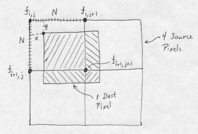
In the figure, fi,j is the value of the source pixel whose UL corner is at the location [i,j] indicated. Pixel vertices are labelled in standard [row,column] matrix notation. Coordinate values increase as you move down and to the right, which is the standard for image processing. Four source pixels are shown, each with their pixel value labeled in its UL corner. Each source pixel is subdivided into NxN subpixels; we show the subdivision only on one of the pixels. We want to determine the value of the dest pixel whose UL corner is at location V, which has coordinates x and y, in subpixel units, relative to the UL corner of the upper-left source pixel. Taking the contributions from the four source pixels in the order UL, UR, LL, LR, the normalized average of the destination pixel, using area averaging, is:
Dest pixel value = (1/N2) [(N - x)(N - y)fi,j + x(N - y)fi,j+1 + y(N - x)fi+1,j + xyfi+1,j+1]
This is the same digital filter that is obtained for linear interpolation when arbitrarily scaling grayscale images!
Fast rotation by Area Mapping
For RGB color images, area mapping interpolation can be slightly sped up (by about 10 to 20 percent) using 4x subsampling (i.e., 16 subpixels), inlining the code for the area mapping for each of the 16 cases, and using the accurate coefficients for the linear interpolation. The constants sum to a power of 2, allowing fast division. (We incorporate the division into the re-positioning of each of the R, G and B components into the destination pixel, so it takes no extra time.) As usual, all operations are done on 32-bit quantities using multiplication, addition and shift.
For most applications, the loss in accuracy (relative to the 16 x 16 subpixel version) is minimal, and the rotation speed for RGB images on a 3 GHz processor is about 18 million pixels/second.
Special rotations by 90, 180 or 270 degrees
For orthogonal rotations of 90, 180 or 270 degrees, no interpolation is necessary. They can be done by shears if the image is first embedded at the center of a sufficiently larger image, so that no pixels are lost when they are sheared. But it is also quite simple to do these rotations by remapping the pixel locations — choosing the source pixel that corresponds to each dest pixel and setting the dest pixel to that value — and that is the method used here. Orthogonal rotations can be checked by doing them consecutively four times (two times is sufficient for the 180 degree rotation) and comparing the result with the source. This comparison is easily done using an XOR between the result and source images, and verifying that the result is “zero”; i.e., there are no ON pixels.
180 degree rotation
These are conceptually very simple: each raster line is reversed, pixel-wise, and the lines are exchanged about the midline of the image. The implementation is thus cleanest as a sequence of two functions: pixRotateLR() and pixRotateTB() For the left-right flip, the pixel access functions allow us to do this trivially. When using these access functions, we do not use the SET function unless the value returned from the GET function is nonzero. Therefore, not all the dest pixels will be written, so the dest image must be cleared prior to the operation. It is appropriate to clear the dest in the high-level code.
Let’s look at the low-level part of the left-right shift operation in more detail. For image depth < 8 bpp, it is more efficient to extract bytes and use a lookup table to reverse the pixels in the byte. This is particularly important for binary images. However, because each raster line begins on a 32-bit word boundary, but does not necessarily end on one, before selecting the bytes for reversal, we must right-justify the raster lines on the 32-bit word boundaries. This is most easily done by shifting the entire image as a block, using an in-place horizontal rasterop. The code for a binary image is:
extra = w & 31;
if (extra)
    shift = 32 - extra;
else
    shift = 0;
if (shift)
    rasteropHipLow(datas, w, h, d, wpls, 0, h, shift);

databpl = (w + 7) / 8;
bpl = 4 * wpls;
for (i = 0; i < h; i++) {
    lines = datas + (h - 1 - i) * wpls;
    lined = datad + i * wpld;
    for (j = 0; j < databpl; j++) {
        if (val = GET_DATA_BYTE(lines, bpl - 1 - j))
            SET_DATA_BYTE(lined, j, tab[val]);
    }
}

if (shift)
    rasteropHipLow(datas, w, h, d, wpls, 0, h, -shift);
The second rasterop restores the source to its normal left-justification on word boundaries. The table supplied here reverses the bits in a byte. For a 2 bpp image, a different table that reverses the four 2-bit pixels within a byte must be used. Note that as mentioned above, if the value of the byte is 0, we do not bother to write its reversed value to the dest. Such tests before setting are particularly useful with binary images of scanned text, where most of the image is background (white) and the majority of bytes have zero value. This rotates each binary pixel in about 5 machine cycles.
90 degree rotation
The 90 degree rotation can be either clockwise (cw) or counter-clockwise (ccw). We specify the direction (1 for cw, -1 for ccw) in the function call.
The 90 degree rotation, like the 180 rotation, is conceptually trivial: we scan pixels in the source and copy them to the dest. As with the 180 degree rotation, the dest must be cleared in advance. In our high-level code, this is implicit because the dest is always calloc\’‘d. It’s usually convenient to organize the two loops by considering the scan for the dest pixels, and one needs to decide in which direction is to be the fast scan. If we’re simply plucking pixels from the source, it doesn’t really matter. Either the source or the dest will have a fast scan direction jumping through the image data. This will cause secondary cache misses, resulting in main memory fetches, but it’s not too serious and takes some effort to ameliorate.
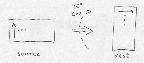
Choosing the fast direction in the dest to be horizontal, for cw rotation we have the following simple algorithm:
for (i = 0; i < hd; i++) {
    lined = datad + i * wpld;
    lines = datas + (wd - 1) * wpls;
    for (j = 0; j < wd; j++) {
        if (GET_DATA_BIT(lines, i))
            SET_DATA_BIT(lined, j);
        lines -= wpls;
    }
}
In the following drawing, the arrows show the first line scanned in the fast scan direction in the source and dest images. I always let the index i label the dest rows; i is in the outer loop because it is the slow scan direction. The fast scan direction, j, labels the dest columns and the source rows.
However, particularly for binary images that have mostly OFF pixels, the fast scan direction through the source image matters, because we can eliminate all computation related to any source byte or word that is 0. Therefore, we want the fast scan in the source to be horizontal (i.e., by rows); this requires the fast scan in the dest to be by columns:
for (j = 0; j < wd; j++) {
    lined = datad;
    lines = datas + (wd - 1 - j) * wpls;
    for (i = 0; i < hd; i++) {
        if (GET_DATA_BIT(lines, i))
            SET_DATA_BIT(lined, j);
        lined += wpld;
    }
}
This is illustrated as follows:
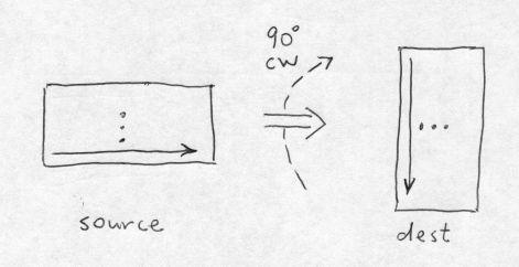
Note that the index labels i and j have been switched from the previous algorithm, because the slow-scan outer loop j labels the dest columns, and the fast-scan inner loop i labels the dest rows.
To take advantage of situations where most pixels in binary images are OFF, we must scan through the source in units larger than bits so that we can easily test them. Two obvious choices are bytes and 32-bit words. With bytes, it takes more work to make a decision, but because of the smaller granularity, more bytes (in total) will be eliminated. However, with typical images, it is more efficient to use 32-bit chunks, and we do that as follows:
nswords = hd / 32;
for (j = 0; j < wd; j++) {
    lined = datad;
    lines = datas + (wd - 1 - j) * wpls;
    for (k = 0; k < nswords; k++) {
        word = lines[k];
        if (!word) {
            lined += 32 * wpld;
            continue;
        }
        else {
            iend = 32 * (k + 1);
            for (m = 0, i = 32 * k; i < iend; i++, m++) {
                if ((word << m) & 0x80000000)
                    SET_DATA_BIT(lined, j);
                lined += wpld;
            }
        }
    }
    for (i = 32 * nswords; i < hd; i++) {
        if (GET_DATA_BIT(lines, i))
            SET_DATA_BIT(lined, j);
        lined += wpld;
    }
}
This is just an elaboration of the previous pixel-plucking code, but it is typically about 4 times faster, rotating each pixel in about 7 machine cycles on average. We find the number of full 32-bit words in the source line, and march over them. Each source word is checked. If 0 it is skipped in its entirely; this alone reduces computation by about a factor of 2.5. Otherwise each of the 32 bits is tested and, if 1, is set in the dest. We get another reduction factor of about 1.5 by shifting and masking the word, rather than using GET_DATA_BIT(lines, i). Finally, for each source image line, a scan is made over any source bits not contained in a full 32-bit word.
We can actually make the binary 90 degree rotation arbitrarily complicated. For example, to avoid pixel-plucking, by brute force you can write an inner loop with lookup tables to rotate each 8x8 block of pixels separately. Using 8 bit lookup tables, for each 8x8 block of pixels, you need to extract 8 bytes from the source, construct 8 addresses from these bytes, perform 8 table lookups (each one generating a 32 bit word corresponding to 4 of the 8 dest bytes), XOR the 32-bit words in groups of 4 to get the 8 rotated destination bytes in two 32-bit words, and then set these bytes in the proper location in the dest image. It’s not at all evident that such shenanigans are worth the effort!
In summary, there are a few “angles” to rotation. RBS has flexibility and speed. RBAM has accuracy, and for efficiency requires specific implementations for each depth. Fortunately, RBAM can be made surprisingly fast with relatively simple implementations. The orthogonal rotations (90, 180, 270 degrees) have special implementations for each depth. The 180 rotation is a combination of left-right and top-bottom flips, with the latter being trivial and depth-independent.
- “Unofficial” Leptonica Documentation Release Notes
- The Leptonica Image Processing Library
- README
- Version Notes for Leptonica
- Source Code and Information
- Source Downloads
- Overview of the Leptonica Library
- Supplemental Notes on Using the Library
- Leptonica API
- /src Directory Contents (API Implementation)
- /prog Directory Contents (Examples)
- Image Processing Operations
- Image Processing Applications
- Byte Addressing for Efficiency and Portability
- What is “Well-Tested” C Code?
- Some Issues in Software Design
- Selected Papers on Image Processing and Image Analysis
- About the Copyright License
- What is the Significance of the Name “leptonica”?
- Glossary
- Leptonica & Visual Studio 2008
- Other Topics
